Mon, Dec 2, 9:35 AM CST

Renderosity Forums / Poser - OFFICIAL


Welcome to the Poser - OFFICIAL Forum

Forum Coordinators: RedPhantom

Poser - OFFICIAL F.A.Q (Last Updated: 2024 Dec 02 5:01 am)


Subject: wave without wave-deformer (part 2)


ernst_h ( ) posted Tue, 20 April 2004 at 1:58 AM · edited Fri, 30 August 2024 at 6:45 AM

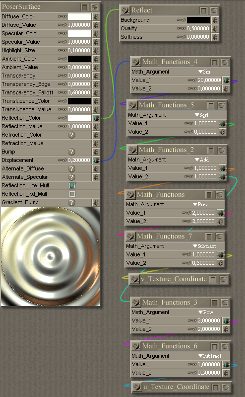
file_106502.gif

You can use a shader which is the representation of the following expression:

sin(20* sqrt(sqr(2u - 1) + sqr(2v - 1)))

If you want more ripples you can increase the 20 to
a higher value.

This wave, however, is not perfect since its amplitude
remains constant with increasing distance wereas a real
wave decreases.

I hope you can use it for something usefull.

Ernst


c1rcle ( ) posted Tue, 20 April 2004 at 3:32 AM

not being a whiz in the material room I don't know, but is there a way with Math function to divide the amplitude by distance from centre? that should decrease the size of the wave as it gets further away from the centre.


ernst_h ( ) posted Tue, 20 April 2004 at 5:52 AM

file_106503.gif

>not being a whiz in the material room I don't know, but is there a way with Math function to divide the amplitude by distance from centre

Sure.
I also added another node Math_Functions_11 to
change the phase of the sin. Just enter something
in value_2

By the way, the renderer seems to have an error.
In the middle of the plane there is always this little
tip, no matter how the phase is.
Do you think I should report this to CuriousLabs?

Ernst


c1rcle ( ) posted Tue, 20 April 2004 at 6:33 AM

yeah let them know maybe they'll have a way to get round it, there's been no mention of another SR release on the horizon so it's probably unlikely to be fixed before Poser6.


WeirdJuice ( ) posted Tue, 20 April 2004 at 7:30 AM

I haven't checked all the way through the shader, but I think that the "tip" at the center is a divide-by-zero effect in the Math_Function_9 node when both the u and v coordinates have values 0.5 where the output from the sqrt (Math_Function_5) is zero. Mathematically, you should test for this value and use the identity sin(x)/x -> 1.0. Bill


WeirdJuice ( ) posted Tue, 20 April 2004 at 7:38 AM

More specifically that should have been: sin(x)/x -> 1.0 when x -> 0.0 Rather than a bug report, CL should get a bit of credit for not crashing Poser when the nodes have a divide-by-zero feature. Bill


gmadone ( ) posted Tue, 20 April 2004 at 7:50 AM

The tip looks normal to me the wave needs to start somewhere, if you use cos, and start from zero, it should look ok. (You need to rotate turn for sin to start smooth) I recommend using 6.28319 for value 1 in all the trig nodes (sin, cos, tan) this way it will cycle at 1. And I adjust the wave count, on the node before (an add or subtract) (you can also animate the wave from value 2 of this node by attaching the frame number) (node 11). Just to clarify nodes 6 and 7 are the center. Node 5 is the Radius, and node 2 is the Radius squared (I use one or both of these for my dampers). And I am not sure, but I think a multiply might be faster than a POW with value 2 = 2. (When you animate three of these together, and then ray trace through them, all the clock cycles count) Hope this helps, Gary


ernst_h ( ) posted Tue, 20 April 2004 at 8:07 AM

file_106504.gif

>but I think that the "tip" at the center is a >divide-by-zero effect in the Math_Function_9

Well, it is not. But I did try a divide by zero on purpose
and Poser did not crash!

The wave-shader represents the following formula:

sin(40 * r) / sqr(r+1)
r (the radius) is the value of Math_Function_5.
It goes from 0 to 1. So, r+1 goes from 1 to 2.
But, as mentioned above, even without that shift
Poser doesn't crash, but renders the above picture.
The hole in the center is really a result of a div by 0.

Ernst


gmadone ( ) posted Tue, 20 April 2004 at 8:14 AM

From the last post it looks like the displacement is larger than the minimum displacement bounds, just move that up 1 or 2.


ernst_h ( ) posted Tue, 20 April 2004 at 8:46 AM

minimum displacement bounds

??? Never heared of that. Where do I find them?
But if you divide by 0 the result is
infinite, anyway.

By the way, you can download this thing and play
around with it yourself now:
http://www.jasms.de/diverses/poser/downloads/wave.mt5

Ernst


gmadone ( ) posted Tue, 20 April 2004 at 8:56 AM

In the Render Options. You didn't divide by zero, and as long as the displacement bounds are not to large, poser will ignore it even if you did.


WeirdJuice ( ) posted Tue, 20 April 2004 at 9:06 AM

Minimum displacement bounds are a rendering setting that allows the render to account for displacements that cross the boundaries between render buckets, although trying to account for a (possibly near) infinite displacement may not be worth the trouble. You're right about the formula, the additional bias does eliminate the possibility of divide-by-zero problems. On the other hand, it does occur to me that any sinusoidal function (or cosines for that matter) would inherently suffer from discontinuities at a radial center. If you take any cross-section of the curve through the radius, it's obvious that, except when the phase is other than +/-PI/2 (?), there is going to be a sharp peak or trough at the origin with the cross section reflected on both sides. This may be a lot more apparent with displacement, since the accuracy of the sampling is always a pixel or less, than with other (geometrical deformation) techniques where there is an element of mesh smoothing between sample (vertex) points. It may be that you need to add an additional smoothing function to compensate for the discontinuity at the center. Bill


gmadone ( ) posted Tue, 20 April 2004 at 9:08 AM

file_106505.gif

I have several animated versions of this. It makes awsome water when its raytraced.


xantor ( ) posted Tue, 20 April 2004 at 12:22 PM

How do you animate this effect? I should point out that I don`t know the mathematics. So a simple explanation would be nice :)


gmadone ( ) posted Tue, 20 April 2004 at 4:39 PM

file_106506.gif

I am not sure how to explain without the math. Hope this example helps. It is set to cycle every ten frames. The trig functions Sin and Cos are wave functions and will cycle smoothly, if the math is done right. Turn off skip frames and press play in the material room the nodes will animate. I have several animated shaders (IM an address and I will Email, their not in free stuff, yet).


xantor ( ) posted Tue, 20 April 2004 at 8:00 PM

Thank you, I will wait till they are in freestuff.


ernst_h ( ) posted Wed, 21 April 2004 at 12:38 AM

file_106507.gif

>On the other hand, it does occur to me that any sinusoidal function (or cosines for that matter) would inherently suffer from discontinuities at a radial center. If you take any cross-section of the curve through the radius, it's obvious that, except when the phase is other than +/-PI/2 (?), there is going to be a sharp peak or trough at the origin with the cross section reflected on both sides.

But look: Math_Functions_9 is directly connected to
the displacement. M_F_9 is smooth, the preview and the
final render are not.

M_F_11 (not shown here) can change the phase of the sin.
But this tip remains always, no matter which value I enter
there.

Ernst


bikermouse ( ) posted Wed, 21 April 2004 at 4:26 AM

bookmark.


gmadone ( ) posted Wed, 21 April 2004 at 8:52 AM

If you change the sin to cos and set the offset to zero, the render will look right, and the preview will have the tip (it does look backwards to me too). If that is not an option try the value .03927 as the offset. The 40 multiplier in the sin node makes that calculation tuff. (I already recommended changing it and using node 11 for the wave count). Hope this helps


WeirdJuice ( ) posted Wed, 21 April 2004 at 10:54 AM

file_106508.gif

Actually the problem there is with the quality of the preview of Math_Node_9 (divide) and Math_Node_4 (sine) rather than with the output. A fundemental problem with the math nodes is how to represent arbitrary numerical output as colour intensity, and in the PixelsDigital/Poser material system, they seem to have gone for simply representing values of 0.0 or negative as black (greyscale = 0) and values of +1.0 or greater as white (greyscale = 255), with the intermediate numerical values translating to linear steps between 1 and 254. This is in fact the internal way that colour values are represented in most graphics programs nowerdays. Unfortunately maths functions are by no means constrained by these values (0.0 to +1.0) and therefore there's always the potential that the preview output will not represent a lot of detail from the function. Hence, a pure sinusoidal function which outputs values between -1.0 and +1.0 previews black in all the regions where the function outputs negative values. Furthermore as the gradient of the function output is greatest as it passes zero, there is a very fast (narrow) transition band of intermediate grey values to the high intensity (near white) colours. This is why in your material setup the sinusoid function previews as apparently strong bright bands, rather than a smooth transitional curve even though it does generate a smooth (and discontinuous) displacement when plugged into the shader. The displacement is a signed function so it uses negative values even when the display preview of the maths nodes always represent these as black. In the above setup, running a colour picker over the preview window for node 4 does confirm that much of the preview output for that node is zero (pure black) and while there is a transition from black to high brightness at the band edges, this is extremely sharp because its at those points where the sinusoid output crosses the zero value that the function gradient is at its maximum. Node 12 scales and biases the divide/sinusoidal ouput so that it has positive values and although I've saturated it by adding a bias of 0.8 for visibility rather than 0.5 it does demonstrate that the maths functions are generating values that are not visible in their own preview windows. More specifically, the "tip" is actually visibly present in this node's preview. Because the tip actually has a negative value (even though its sticking up in the displacement) at the output from the divide node (9), it's colour is black and its not visible in that node's preview. Moreover its important to realise that, when it comes to the visibility of features in displacement and bump mapping, its not the actual height of the displacement that matters, rather its the gradient and change of gradient at the discontinuity. Therefore the worst case actually occurs if the discontinuity from a sine function has a displacement value of zero as this is the point at which the gradient of the function, and hence the sharpness of the "tip" is at the maximum. Bill


Privacy Notice

This site uses cookies to deliver the best experience. Our own cookies make user accounts and other features possible. Third-party cookies are used to display relevant ads and to analyze how Renderosity is used. By using our site, you acknowledge that you have read and understood our Terms of Service, including our Cookie Policy and our Privacy Policy.